

The following lists some of the methods that can be used to measure with PhotoModeler in difficult circumstances. The list corresponds to the set of example problems above.
• Some projects require more planning than others. To remove the car problem, one needs to go out on a weekend and put out some pylons to stop cars from blocking the view of the bottom of the building.
• Sometimes it is necessary to get the camera into a high position to be able to shoot down over obstructions like berms, hedges, etc. If there are nearby buildings one can use them and shoot from upper story windows or the roof. If there are no surrounding buildings one can sometimes use a tall step ladder, stand on top of a car or truck, or rent a lift for the day. Again some preplanning of the Measurement Project will let you know what restrictions you will have to overcome. It does not matter if photographs are taken from different elevations; in fact, that is preferred.
• For some types of obstructions and some types of objects one can use extender bars. An extender bar is a long piece of straight wood or metal with three or four marks on it. They are measured with a tape measure so the distances between the marks are known. The bars are then placed in the scene being photographed so two or three of the marks can be seen by multiple shots of the camera. The last mark is placed beside or on top of the real feature you want to measure (for example, where the boiler meets the floor). In PhotoModeler you mark the points on the extender bar that can be seen in the photographs. In the CAD program you extend a line from those marks by the pre-known distance to the point you want the measurement for; see the diagram below:
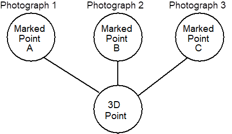
The two upper marks can be seen and measured. The third mark can be projected from the positions of the other two and a known distance. This is quite easy to do in most CAD programs. You would not want to do this for very many points but when you are stuck it can be helpful.
Edges may also assist with this situation.
• Trees and vegetation can sometimes be difficult . The best time to measure this sort of structure is in the winter because of the lack of leaves! Often you cannot wait that long. With careful layout and planning of the camera shots, use of extender bars or other object features, or the use of a wider angle lens one can often measure in these circumstances. The Edges feature is also very useful in this situation if you have the correct photography.
• To measure the top of something, you will need to get above it; there are not many ways around this problem. You can try to get up on a nearby tower or building, you can use a airplane or helicopter, or you can use some sort of lift. We have had suggestions of using balloons and remote control model helicopters but these are only for the seriously adventurous.
• Measuring and modeling surfaces such as milled and cast parts or terrain is a similar problem to the previous one. You need to provide a set of unique points that can be identified precisely in the photographs. With a small part you can project a pattern on to it (i.e. with a slide projector or laser) . With a larger part you can stick items to it or put on paint or wax marks. With a large surface (such as a pile of rubble) you might need to throw down some traffic cones with large numerals written on them. See the section Using Targets for more information on adding points to scenes.
• Create a sheet of paper or other suitable platform with printed or placed circular targets under the object (or as a background). Then use the Sub-Pixel Marker to mark these targets (at least six per photo), reference them and then process. These points while not needed for the final model will produce accurate station orientations so that tools like Cylinder, Edge and Curve can be used to do the actual modeling.
• Modeling a large object in which a lot of small detail is also required involves taking photographs at least two different scales. A few (3-4) photographs are taken encompassing the whole object or building. From these photographs an accurate but a model low in detail can be built up. At this stage one of two approaches can be taken:
• If there is an overall higher level of detail required, take a set of overlapping close-up photographs. Mark and reference these to each other and to the overall photographs. Both the distance and close-up photographs can be combined in the same project.
• If small sections of very high detail are required you can do these areas as individual PhotoModeler projects. To tie the detail models together, use the overall low-detailed model as a source of control points to orient the detail models. That way all the detail models will sit in the same coordinate system as the overall model. The models can then be combined in CAD.
• When a large structure cannot be photographed in whole then it should be photographed in pieces with good overlap between photographs. The more overlap usually the better as far as accuracy goes but the more pictures that need to be taken and the greater the amount of referencing. It is a trade off. Below is a diagram of a large facade and the light rectangles are the areas of the photographs taken.
Using photograph overlap to capture a large structure