

Perspective Matching is the process of determining the position of a camera when it took a photograph so that 3D graphics can be combined with that photograph and ‘match’. To combine 3D graphics with a photograph in a 3D rendering program you have to indicate where to place the camera, how to orient the camera, and what are the specifications for the camera’s internals. When this information is accurate, the rendering will match the background image/plate for a high degree of realism.
When PhotoModeler is solving a project to create a 3D model, it computes the exact position and orientation of the camera for each photograph. It also knows the accurate specifications for the camera’s internal parameters (focal length, field of view, etc.). This information can be exported from PhotoModeler for use in rendering and animation programs (such as Maya, XSI, 3D Studio Max, Truespace, Cinema 4D, Real3D, etc.) .
The example below starts with an image of a cardboard box of known dimension. On the other hand we know nothing about the camera that took the photo - we don't know what type of camera, what its focal length is, or where it was in space when the photo was taken. In this case we use another feature of PhotoModeler called Inverse Camera.
PhotoModeler’s Inverse Camera feature and control points (control points are known x,y,z locations) are used to solve the camera parameters and orientation. That information is then given to the Real3D animation/rendering program along with the 3D box model to perform a perspective match and rendering.
Note that control points and inverse camera are used in this example because we have a single frame from an unknown camera, but perspective matching can be used with normal projects with calibrated cameras too.
The steps of this example are as follows:
1) Start with an unknown photo of a box and import into PhotoModeler.
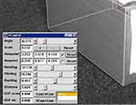
2) Load the known control points (box corners) and mark them on the photo in PhotoModeler. Solve the project and then export the camera station information (see Output to Printer, Clipboard or File for information on exporting data from the Photo Table (export shown below in Notepad)). Note that if using Rhino, Maya or VRML export formats the camera data can be exported along with the model data making the setup in Maya or other program easier.
3) In the rendering program (Real3D in this case) load the box model from PhotoModeler and then set up the camera given information from PhotoModeler.
4) Add graphical elements to the box scene.
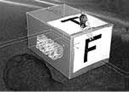
5) Render the result using the original photograph as a background. See how the perspectives match and how the shadows of the objects fall correctly on the box.

If you are using a calibrated camera you can achieve a better match by removing lens distortion from the images. The mathematical model of the camera used by rendering programs is ‘ideal’ and typically does not account for lens distortion, non-centered principal point, or non-square pixels. PhotoModeler’s Idealize feature (see Idealize Project) provides a function for removing all these distortions from the images and the solutions for the model and camera stations. You would run Idealize Project before the export and then you will find your matches in your rendering program can be very accurate.
See also Using your 3D Model with another program and Importing and Setting Up Coordinate Systems for other pertinent information.