
•

This section controls what type of objects are visible in the associated 3D Viewer. This section encompasses non-surface types.
|
Points |
When this box is checked, all 3D Points in the project that have solved xyz positions will be drawn as small squares using the diffuse color of their assigned material. Note that if photo-textures are enabled (Fast or Quality, see Surface Types Display Style setting) the Surface Draw Points will appear with a colour extracted from a photo (according to the Material assigned to the point). |
|
Point Tags |
When these boxes are checked, all 3D Points in the project that have been tagged are displayed with a ‘T’ for tag. |
|
Point Confidence Region |
When this box is checked the error ellipsoid is displayed for each point. This object shows the confidence region (also known as Error Ellipsoids) for the point. Normally these are so small you will need to use the Point confidence region scale factor in the Sizes section of the 3D View Option to see them. |
|
Offset Points |
When this box is checked, all valid Offset Points (i.e. those associated with 3D Object Points) will be shown. |
|
Surface Draw Points |
When this box is checked, the points associated with the drawn Surface Draw features are shown. Note that if photo-textures are enabled (Fast or Quality, see Surface Types Display Style setting) the Surface Draw Points will appear with a colour extracted from a photo (according to the Material assigned to the point). |
|
SmartPoints |
When this box is checked, the SmartPoints will be shown. Note that if photo-textures are enabled (Fast or Quality, see Surface Types Display Style setting) the SmartPoints will appear with a colour extracted from a photo (according to the Material assigned to the point). |
|
ID’s |
When this box is checked, all 3D Points in the project are displayed with their ID number (perhaps user name too). Coded Targets have a unique set of ids and the id is shown in square brackets: [1002] is point id 1002 and code 2. Available only when at least one type of point is checked. |
|
Lines |
When this box is checked, all Lines that connect solved 3D positions will be drawn as vector lines using the diffuse color of their assigned material. |
|
Outlines |
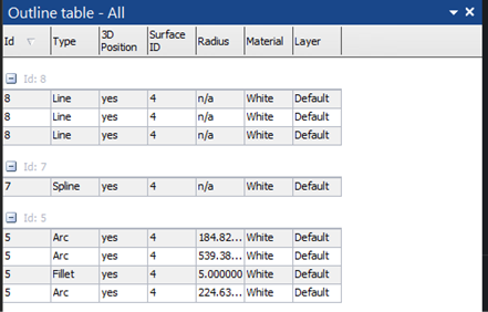
When this box is checked, all Outlines that are 3D will appear. |
|
Surface Draw Lines/Curves |
When this box is checked, all Surface Draw (lines and curves) that have solved 3D positions will be drawn. |
|
Curves |
When this box is checked, all Curves that are 3D will be drawn as curved lines using the diffuse color of their assigned material. |
|
Edges |
When this box is checked, all Edges that have a solved 3D position will be drawn a vector lines using the diffuse color of their assigned material. |
|
Edge end points |
When checked Edge endpoints will be shown, which allow you to use the endpoints like other 3D points and can have surfaces and lines attached to them. |
|
Camera Stations |
When this box is checked, Camera Stations that have been solved (the location of the camera when it took each photo) will draw as either a symbol (a box with lens cylinder), or as an image plane (when the Image Planes box is checked).
The size of the symbol and the size of the image plane are affected by the Camera Station symbol size in the Sizes section of the 3D Viewer Options. The Image Planes are a great illustration and quality check tool - esp. along with Light Ray display (see Quality Tools section of 3D Viewer options). You can also show camera station symbols while image planes are visible (option enabled when Image planes are checked).
Frustums, the three-dimensional region which is visible in an image, can also be made visible. The frustum distance can be set in the Sizes section.
When Rays… is checked, this displays one or more vectors from a point to a camera station when an item is selected. If a point is selected, then all the light rays for where that point is marked are shown back to the corresponding camera stations. If a camera station is selected then all the marks on its photo are shown with light rays. Multiple points and multiple camera stations can be selected at once. This is an excellent demonstration, debugging and quality checking tool. |