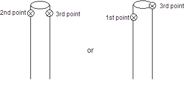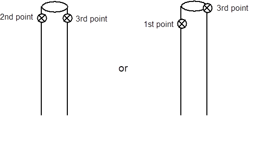

Offset points are 3D point positions that are defined based on the position of one or more existing Object Points. Offset points create a ‘shadow point’ of their associated object point, moving and updating their positions as the Object Point changes. An Object Point can have multiple offset points.
There are several types of offset points:
• RAD offset - a point offset from two RAD target points. RAD offsets are set up when generating/printing RAD coded targets (see Create Coded Targets Dialog), and when applying the offset range to your project (Coded Target Presets, Coded Target Offsets Library). A RAD offset point is generated from two RAD target points in the offset range as set using the Offset Point Range Dialog. Only those RAD targets within the defined range will generate offset point. The vector, defined by the first odd numbered target ID and the next consecutive (even) target ID is used as the direction, while half the distance between the two target id’s is used as the offset distance from the even target ID. In other words, the RAD offset point is placed ½ the distance between the two targets beyond the even coded target ID along the vector defined by the two target points.
• Axis offset - a point offset from another along a vector parallel to the X, Y or Z axis. An axis offset point is defined on the Object Point Properties Pane or dialog. There are two ways to adjust the distance of the offset: using Properties or, a handy feature of Axis offsets is that the offset point can be dragged on a photo along the chosen offset axis (e.g. using an Z axis offset on a Surface Draw point to measure the height of a person or object over a defined surface).
• 2 point offset - point offset from another using two points as the vector defining the offset direction. A 2 point offset is defined in the Object Point properties for the first point. The ID of a second point that defines the direction is also entered. These offsets are useful for defining corners or other places where dot targets would be hard to place. 2 point offsets are also used when setting up your Coded Target Offsets Library.
• Custom offset - an offset point defined by a set of saved properties that can be reused in all your projects - for example when using offset points with Evidence Markers. You define a custom offset using Edit Custom Offset Types (a link visible in the Object Point Properties dialog when the 'Offset type' field is chosen).
Offsets are set up using the Object Point Properties dialog or pane. You can also set up groups of offset points that can be reused from project to project using the Coded Target Presets tool, or Coded Target Offsets Library.
To create an individual offset point you first select an object point and use the Properties Pane or dialog box to define the parameters for the offset. Then select the Offset Point(s) property which will reveal the “Add a new offset”, then define an offset type and distance (unless you are using RAD offsets).

In the screen capture shown above, Point #1 has been assigned an X axis offset type. Once the type is selected, the parameters of the offset are shown in the expandable Offset point section.
Multiple offsets can be assigned to a 3D point. Select “Offset Point(s)” property then click the “Add a new offset” hyperlink to add one to the selected point.
The Edit Custom Offset Types hyperlink shows when the offset type is selected. A distance of 2.00 (in project units, can be positive or negative) has been entered and the material and layer are selected. By default the offset point uses its associated point’s material and layer, but an offset can have its own distinct material or layer.
Once the offset has been defined, it will appear in the Offset Point Table, the 3D Viewer (if the “Offset Points” option is checked on the Vector Types page of 3D Viewer Options Dialog), and as a 3D point on photos (if the “3D offsets” option is checked on the Visibility on Photos pane, see Visibility Settings).
Note: The project’s coordinate system must be defined (either Scale/Rotate or Control Points) for the offset points to calculate their 3D position, and an offset point’s associated object point must have a 3D position.
For example, if you had a target as shown in the examples below, and you are interested in the point on the road surface (e.g. to create a surface on the road plane), you could use an Axis Offset and define an offset point to be created down the Z axis using the height of the target off the ground (as long as you know the exact distance from target center to the road surface, and you define the model’s rotation such that the ground is the XY plane and the Z axis is vertical):


A 2 point offset is a point offset from another using two points as the vector defining the offset direction. You define an offset direction based on the vector between two points, this is called a 2 point offset. For this type of offset you enter the ID of a second point that defines the direction of the offset, which can be useful for defining corners like this:

In this example, the point in the foreground (Point #1) would be assigned a 2 Point Offset type using the point in the background (Point #2) as the second point ID. You would use the known distance between Point #1 and the tip of corner as the distance or value of offset (e.g. 3cm). As long as Point #1 and #2 have valid 3D positions (and the model’s coordinate system has been defined, this offset setup would create a 3D offset point at the tip of the corner using the line between the points as the direction vector (red dashed line shown above).
This allows highly accurate point marking, using targets, where normally a target could not practically be placed. Offset points can be used like regular points for creating lines, surfaces, curves through points, measurement, etc.
By default offset points will use the same material and layer of the object point they are offset from but you can set specific values for the offset point.
If you repeatedly use a specific offset distance and axis, you can create a custom offset type using the Edit Custom Offset Types dialog and assign this to the appropriate object points. A custom offset has a preset distance and axis type, which means you do not have to define the type of offset for each point.
You can also automatically setup a series of reusable two point coded target offsets (or RAD target offsets) using the RAD and Coded Target Offsets command (on the File tab’s Print > pane).