

This applies to workspace dedicated to template/pattern modeling where the camera is permanently mounted over a work surface (e.g. floor or table), for example:
When the camera is mounted (typically ceiling mounted pointing down, but could be on a wall facing a parallel wall), a Base Project must first be created. The Base Project is reused for repeated template pattern digitizing on a dedicated work surface.
This instructional video outlines the workflow: Mounted-Camera Setup video
You can either create the Base Project yourself (much of it automated) or use the Send button to upload the data to PhotoModeler Technical Support and they will create it for you and send you the result. Also see the web page Submitting 2D Template Pattern Capture Base Projects to PhotoModeler. In either case, the following steps must be carried out first to get ready.
First, you need to mount the camera and take a photo to establish the field of view and to know the extents of the work surface that is captured by the camera. Mark the approximate corners of the image frame on the work surface with tape or markers so you know where to contain the targets and eventually the template pattern, something like this:
Next, click ‘Print target sheets...’ to send a series of targets to your printer. The printed targets need be taped down onto the work surface in a specific order, as shown below, where target 1 is at top left, target 8 is top right, target 25 is bottom left, and target 32 is bottom right (ID of targets shown on the target printouts):
Note that the sheets can be landscape or portrait orientation as long as the sheet order is correct. Also shown in the image above are a handful small dot targets or X’s that you’ll want to permanently place on the work surface. These points are used to verify that the camera and/or workspace haven’t shifted between when Base Project was created and when doing the digitizing of the patterns later.
Make sure none of the targets move when taking photos. They should be properly affixed to the work surface.
Next, remove the camera from its mounted position, and take 12 photos from camera positions similar to a calibration (see Taking the Calibration Photos).
Next, remount the camera and take one top-down photo from the mounted position. There should be a way to transfer photos from this camera to a computer so that the camera doesn’t move between projects (e.g. a wired USB connection, or Wi-Fi image transfer).
Using a tape measure, carefully measure and note the distances between the centers of these target pairs:
• #1 and #8
• #3 and #30
• #8 and #25
• #5 and #29
• #17 and #32
You’ll need these distances to set the scale of the Base Project, an important step! At least the first 3 measurements are needed, 5 is better.
With the photos and measurements, you’re ready to launch the project – click ‘Run base project set up…’ or ‘Send Photos and Measurements to PhotoModeler…’:
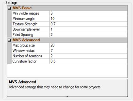
Whether you’re sending the photos and data to PhotoModeler for processing or running the project yourself, the next steps are similar.
Click Add Photos… to add the 13 photos. Set the units of your measurements and enter your scale measurements between the specified targets. Then click to select/highlight the top-down mounted camera photo thumbnail. Verify the photo is correct as shown beside the “Photo from mounted camera”.
Click Process to run the Base Project, or if you’re sending the project data to PhotoModeler, a field is available where you enter your email address and upload the files.
When running the Base Project, a summary of targets marked, and processing results will be shown.
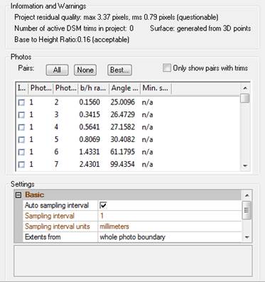
After you click ‘Done’, you will be prompted to mark the check locations of the permanent targets:
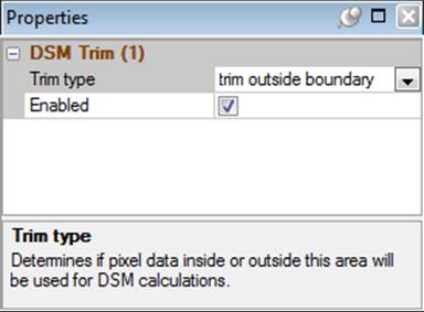
The project will be reduced to the single top down photo and the photo will display, on which you can now mark the permanent check points, for example:
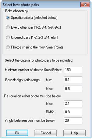
After the check points are marked, save the Base Project.
Once the Base Project is defined (or returned to you from PhotoModeler Support staff, usually within a couple business days), just a single photo of each template pattern will be needed, on which the template pattern is traced either in PhotoModeler or in some other CAD application using a corrected photo (see Digitize New Template Pattern).