

The third control sets the zoom factor. The ‘Output zoom factor’ controls how the image pixels will cover the output image. For the default value of 1.0, the output is sized so that all original source image pixels remain in the output image. This means that some part of the resampled input will touch at least one edge of the output image. Note it may not touch all edges, depending on the principle point and the decentering distortion of the original camera. Cameras with high distortion can have big black border areas and not as much useful image data.
As the zoom factor goes above 1.0, the black border will be smaller, and some of the original image pixels will be outside of the output image. This may be desirable to get the best coverage for what you want to see in your output. You can reload the original project and try different zoom factors to get the output coverage you want.
The following example shows the output image extents at various zoom factors:
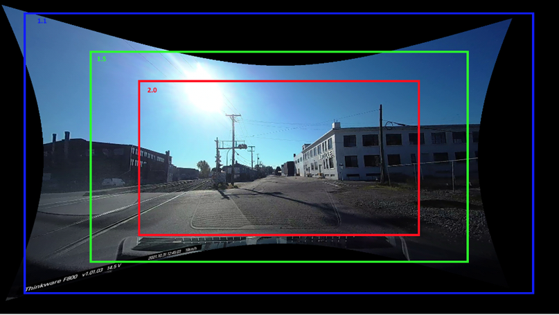
A zoom factor of 1.0 (the full image above) captures the whole input image in the output (with one or more corners of the original pixels touching the edges of the output image). The more distorted the original image, the larger the black borders seen in the output.
The zoom factor is relative to the 1.0 default zoom. A zoom factor of 2.0 produces an output image that is half of the 1.0 zoom output - that is, half in with and height. Those pixels are then expanded to fill the whole output image. Another way to describe it is a zoom factor of 2.0 will have a quarter of the pixels that the 1.0 zoom output image does. Similarly, a zoom factor of 3.0 will have a third of the zoom 1.0 image in width and height, and will have a ninth of the pixels that the zoom 1.0 output does.
Typically, you will need to run Idealize at least once at the 1.0 default zoom to see the result, and then you can estimate how much you want for your next run. You will need to reload the un-idealized project to run Idealize again. During these multiple runs you may want to reduce the number of images being processed by using a Photo Set and reducing any image sequences you might have.
Note that regardless of the zoom factor, the project will be still in an ideal state with all the marks moved to correct locations, etc. You can do exports, process the project, view all the tables, 3D, etc. Think of it like a zoom lens on a camera. You see less of the scene but more detail with a higher zoom factor. Here though, after idealizing, the camera is an ideal camera with no lens distortion and a centered principle point (as needed in most CAD packages).
If the zoom factor is high, some of the marks on the photos may end up outside the resulting photo and you won’t be able to see them (although they are still there). For some marks like normal point marks, you can still see them in the 2D Point Table. With other objects marks (cylinders, curves, edges) you may no longer have access to them if they are pushed outside of their photo. A warning message will appear after Idealize if any photo marks are now outside the photo boundaries. When using higher zoom factors, and if marks are pushed outside the boundary, you may not want to use this project for much further processing or development. Do all your modelling work in the normal un-idealized state and only idealize just before you need the results for output to CAD etc.