
A rotation controls how the model is aligned to the x,y and z axes. Without a rotation defined, the ‘top’, ‘right’, ‘front’, etc. of the project is arbitrary. A rotation, along with a scale (see setting scale) and translate (see setting translation), is part of a coordinate transformation that can define a project's coordinate system.
A rotation needs two of the three (x,y,z) axes defined, or it can be aligned to a camera view or a plane.

To define a rotation, select the rotate object in the left hand list on the Imports and Coordinate Systems Pane.
To define an axis rotation select two points (from a photo, table or 3d view) in the order specified for the axis you wish to define. For example to define the x-axis first select a point on the left of the model, then hold down shift and select a point on the right. Once the two points are selected, press the “Horizontal-X left to right” button to define those two points as the X axis. Once either the Y or the Z axis has been defined the rotation will become active, the third axis is implied by the first two. Note that if the rotation axis is flipped using two points, you can reselect the points in the opposite order and redefine the axis.
You can also use planes (see Creating Planes), edges (see Edge Defining/Modifying) and cylinders (see Cylinder Defining/Modifying) to define a rotation axis. Select the plane, edge or cylinder and press the appropriate button to assign the axis. When using planes, the axis you define is perpendicular to the plane; therefore, the Z axis would typically be defined by the plane (i.e. a ray perpendicular to the plane would define the Z axis), and then two points or a line etc. on that plane would be used to define the X or Y axis.
Note that if the rotation axis is flipped when using an edge or cylinder, you can click the hyperlink "-->" next to the summary item. This will reverse the direction of the axis and flip the coordinate system accordingly.
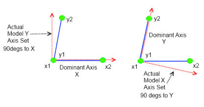
The dominant axis is used to establish the rotation even when selected point pairs defining two axes do not form a 90 degree angle. The following diagram shows how the rotation will be set up where the points selected to define the axes are in green (x1, x2, y1, y2). The left shows the effect on the model axis of making the X axis dominant, while at right the Y axis is dominant:

The third axis will be set to be perpendicular to the plane defined by dominant axis and other axis. In the example above, the Z axis would point out of the screen, perpendicular to the XY plane.
To define the rotation from a camera view select the camera station in the 3D viewer (make sure Camera Stations are visible in the 3D Viewer Options Dialog) and press the ‘Define from camera view’ button. If you were looking at the back of the camera (as you would normally hold a camera to take a snap shot), the X axis goes right along the film / imaging plane, the Y axis goes up along the film / imaging plane, and the Z axis points back towards you.
Multiple rotation objects can be defined, but only one of them can be active at any one time.