

The Imports and Coordinate Systems Pane is used to add information such as distances, x,y,z measurements, coordinate frames, meshes, and 3d models from an outside source to the PhotoModeler project. The external measurements can be manually added or imported from a file (.txt, .dxf, .obj). The external geometry can be used as scales, translations, rotations, point coordinates (for coordinate transform and control), geographic point definitions, pinned and static model imports, and check distances or check points.
Layout of the Imports and Coordinate Systems Pane:
From left to right, starting on the top toolbar, the tools are described:
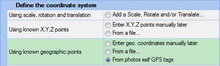
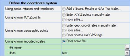
• The add/import external geometry button brings up the Import or Add Coordinate Systems Dialog where the type of data to import is set.
• Deletes the selected external geometry object.
• Renames the selected external geometry object. Clicking this button will activate the name cell in the selected row allowing the name to be edited or a new name typed in. OR for some import types (clouds etc) it brings up the Properties for the import for changing name and other properties (like solving scale for 3d pinned imports).
• Selects the assigned object(s) in the project of the highlighted item and open its photos.
• The units used by the project. The units selected here will be used when displaying any measurement information and will be the default for any measurement input. You can change a project's units at any time.
• Opens the Modify/Convert the Selected Import allowing you to convert between import types, set precision values, and apply or flip (e.g. RHS<->LHS) a coordinate system.
• Note if a pinned Import Object (Premium) is selected one more tool is add to the end as shown below. This opens the Pinned Import Transform dialog.
The Imports and Coordinate Systems Pane can contain any number of external measurements, but only certain types of external data can be enabled together. If enabling an external measurement causes a conflict with a currently active one a warning message will come up allowing you to choose which one to keep activated. For example, since both control data and scale/rotate/translate data both define the coordinate system these types of external measurements cannot be active at the same time. The explorer’s table shows the status of each geometry object, with these columns:
• Active: shows whether the object is active - this is a check box under user control. Click the check boxes in this column to activate or disable external geometry objects. A disabled object remains in the project but does not affect the results (e.g. no change in coordinate system from this object).
• Valid: shows a green check mark when an external geometry object is in a state where it can be used. If this column has a red x the object, the geometry is invalid. See below for further detail.
• Type: shows an icon indicating the type of external geometry: object, scale, translate, rotate, control, pinned, static, or check, with icons as follows:
|
Type Icon |
Description |
Link to Section |
|
|
Scale |
|
|
|
Rotation |
|
|
|
Translate |
|
|
|
Multipoint Transform |
|
|
|
Imported Mesh Multipoint Transform |
|
|
|
Geographic Multipoint Transform |
|
|
|
Control |
|
|
|
Control Point Cloud/Mesh |
|
|
|
Geographic Control |
|
|
|
Pinned Import |
|
|
|
Pinned Imported Point Cloud/Mesh |
|
|
|
Pinned Import (via Surface Draw) |
|
|
|
Static Points |
|
|
|
Static Point Cloud/Mesh |
|
|
|
Check Distance |
|
|
|
Check Point |
•
• Name: the name assigned to the external geometry object, which can be changed using the rename button (3).
Once you import an item, a toolbar specific to that item will appear below the top toolbar. In the screen capture above, the control specific imported object sub-toolbar appears. These toolbars are displayed when an imported control, multipoint transform, pinned or static object is selected. They include tools for marking, selection, and other related tools. See Imports Sub-Tools and Marking/Pinning Multipoint Transform, Control and Pinned Import Points.