

The Define Volume tool is on the Cloud/Mesh Tools Tab.
Volumes are used to identify, calculate and store the volume underneath a user-defined part of a Triangulated Mesh. They are commonly used to get the volume of a stock pile. One solves the project (often from UAV photography – but it is not limited to this), creates a dense surface, and then outlines the area on the surface where the volume is to be computed and stored.
A volume object (yellow) overlaid on the source Triangulated Mesh (white):
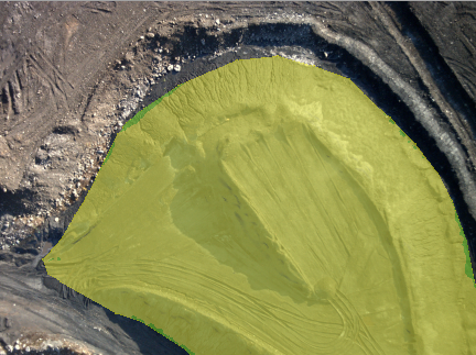
The same volume object visible on a photo:

A Volume object stores a set of 3D triangles defining a top, and a planar base to create a closed volume. Volume objects are created from an outlined region of a Triangulated Mesh. Volume objects are saved with the project and can be retained even when their associated Triangulated Mesh is modified or deleted. When selected, the calculated volume of the Volume object is displayed in the Measure pane. The Properties pane provides settings that control the calculation.
To create a Volume Object:
•
Switch to Define Volume Mode by pressing the Define Volume mode
tool ![]() , or by selecting “Define Volume
Mode” from the Dense Surface menu. The cursor will change to the Define
Volume Mode cursor.
, or by selecting “Define Volume
Mode” from the Dense Surface menu. The cursor will change to the Define
Volume Mode cursor.
• Determine which Triangulated Mesh you want to extract the volume from and ensure it is visible in the photo(s) and/or 3D view(s) you will use to create the Volume object.
• Study how you will the outline of the base of the Volume. Pick the starting point (in 3D view or photo). Left click on the 3D view or photo – on top of the Triangulated Mesh. This click will create the first 3D point of the volume outline where it intersects the triangulated mesh. The mesh will change to be shaded blue and slightly transparent making easy to identify which mesh is associated with the volume.
• Continue left clicking to create new points defining the volume outline. These clicks will create a yellow closed polygon. This polygon defines the boundary for the Volume object.
• The boundary can be created from a single view or across multiple photo and 3D views.
• The boundary is formed in 3D. If a 3D view is rotated/zoomed/panned the boundary outline will also be updated to match.
• If you place an outline point incorrectly, use the right click menu and the “Remove last Boundary Point” option to remove the last point created.
• When the outline is complete, right click and choose “Finish Volume”. The surface within the boundary will be extracted, thereby creating a Volume object that is independent from the underlying mesh.
• Along with the extracted triangles, a volume plane base is computed and displayed. How the base is calculated can be controlled by the Volume Properties. The volume surface is shown in yellow and the base in a transparent green.
• The volume has its own properties, visibility, layer and material. By default, the material is yellow but any material can be used.
• The Measurements Pane will display the volume between the surface and the base plane. See: Measuring Volume Objects.