

Display:
|
Field |
Description |
|
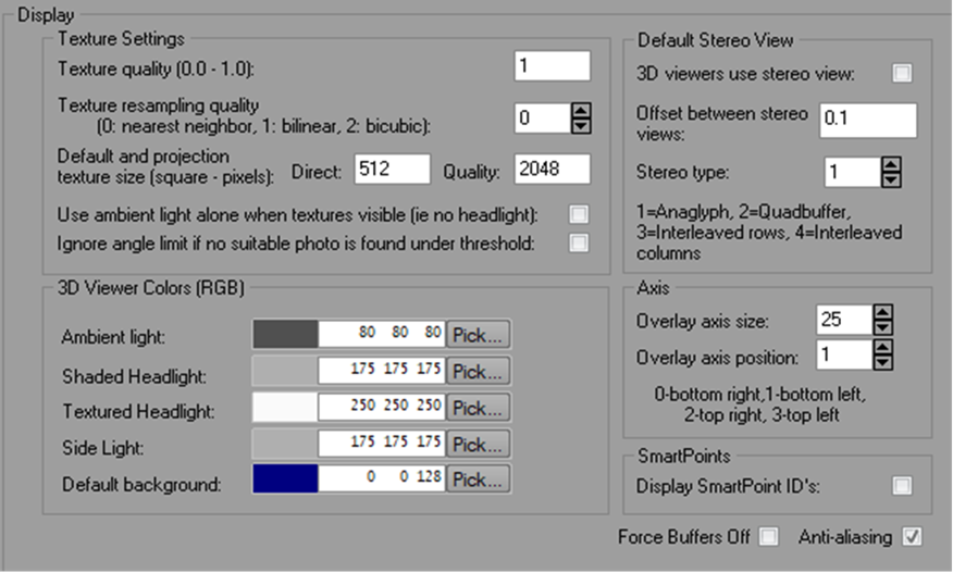
Texture Settings |
|
|
Texture quality |
Controls the quality and rendering speed of the 3D Viewer when textures are displayed. |
|
Texture resampling quality |
Controls what form of resampling is used when texture maps are created by PhotoModeler from photos for the 3D Viewer. Bicubic resampling is the slowest but usually produces the best quality. |
|
Default and projection texture size (square - pixels) |
Controls how large the created texture map files are for the 3D Viewer and for projections. The maps will be square of this size (e.g., 512 by 512). A power of two value will make rendering faster (i.e. 256, 512, 1024, 2048 etc.). The larger the value the better the quality but the slower the navigation. This is only the default for the 3D Viewers for new projects. The size can be controlled independently per 3D Viewer in the 3D Viewer options dialog. |
|
Use ambient light alone when textures visible |
If checked the headlight is turned off when the model is textured. |
|
3D Viewer Colors |
|
|
Ambient light |
The RGB setting for the ambient light in the 3D Viewer scene. |
|
Shaded Headlight |
The RGB setting for the light located at the view camera for the 3D Viewer scene for use when surfaces are displayed as shaded . |
|
Textured Headlight |
The RGB setting for the light located at the view camera for the 3D Viewer scene for use when surfaces are displayed as photo-textured. |
|
Side Light |
The RGB setting for the side light for the 3D Viewer scene. |
|
Default Background |
The RGB setting of the window background of the 3d views in Animations and the Imports and Coordinates panes. You set an individual 3D Viewer background colors on 3D Viewer options (see Settings - Advanced). |
|
Note on Camera Stations |
The color of the 3D Camera Station symbol in the 3D Viewer is controlled by the Material assigned to it. |
|
Default Stereo View |
|
|
3D Viewers use stereo view |
When checked makes each 3D Viewer display a red/blue stereo anaglyph. With the appropriate colored glasses you can see the object in the 3D Viewer “pop” out of the screen. This is the default setting as each 3D Viewer can be controlled independently in the 3D Viewer Options dialog. |
|
Offset between stereo views |
The amount of horizontal offset between the two stereo channels. This is a trial and error value to be set to get a reasonable disparity offset (not too big and not too small). This is the default setting as each 3D Viewer can be controlled independently in the 3D Viewer Options dialog. |
|
Stereo Type |
Used to set the type of stereo display: 1. Anaglyph - Render stereo by superimposing two images of the same scene, but with different color filters over the left and right view (or "eye"). This is a way of rendering stereo which works on any display, using color-filter glasses. Such glasses are usually cheap and easy to come by. 2. Quadbuffer - Render stereo by using OpenGL quad-buffers. This is the most common interface for stereo rendering for more expensive hardware devices, such as shutter glasses and polarized glasses. 3. Interleaved rows - Interleaving / interlacing rows from the left and right eye is another stereo rendering method requiring special hardware. 4. Interleaved columns – same as 3, only it is vertical lines that are interleaved / interlaced, instead of horizontal lines. |
|
Axis |
|
|
Overlay axis size |
Size of the corner overlay axis when displayed. |
|
Overlay axis position |
The corner position of the overlay axis when displayed. |
|
SmartPoints |
|
|
Display SmartPoint ID's |
Include the SmartPoint ID"s when point ID visibility has been enabled. When there is a large number of SmartPoints, showing ID's can clutter your 3D Viewer. |
|
|
|
|
Force Buffers Off |
Check this setting if you’re having 3D Viewer display problems, especially if you are getting error messages specifying “coin” or “openGL”. These types of problems are usually graphics driver related, but this setting can be used if a driver update doesn’t help. |
|
Anti-aliasing |
Controls the display of curves, lines, and surface edges etc. in the 3D Viewer, and with this setting checked they will appear smoother. |
Selection and Navigation:
|
Field |
Description |
|
Mouse Button Navigation |
|
|
Left Button |
One of three actions to assign to each of the associated mouse buttons, 1 for Pan, 2 for Zoom, 3 for Rotate. (see also Mouse Button Reference) |
|
Middle Button (scroll wheel button) |
|
|
Right Button |
|
|
Alt key must be pressed |
When checked the “Alt” key on your keyboard must be pressed while navigating using the associated mouse button down and drag method. When unchecked navigation can be done by just mouse down dragging. Note that selection can still be done provided you do not drag the mouse while selecting. |
|
Selection |
|
|
Selection uses a menu for overlapping items |
When checked and a selection click is done in the 3D Viewer a menu will come up showing all overlapping items that are close to the click location. The menu allows you to pick which is the object you want selected. When unchecked, the selection is made on the “best” choice. |
|
Radius around mouse to search |
Number of pixels around clicked mouse position to search for objects to select (in the 3D Viewer and Control Point Dialog 3D View). |
|
Max depth to search |
Depth of model to search for selection. The longest side of the model is divided by this number and any objects with in that distance will be considered for selection. |
|
Region select to include crossing objects rather than just contained objects |
Include in the selection items that traverse the boundary of the selection region, rather than just the items entirely within the selection region. |
|
Zoom |
|
|
Zoom step size/speed |
Controls the sensitivity of the zoom in the 3D Viewer (both mouse-scroll zoom, and zoom controls at bottom right). A smaller value will allow for finer/slower zooming. |
|
Scroll wheel step size |
Controls the sensitivity of mouse scroll wheel zoom. A smaller value will allow for finer/slower scroll zooming. |
|
Other |
|
|
Holding Control while rotating |
Constrains the rotation of the model to the selected planes. |
|
3D Views have non-modal visibility tab |
When checked a tab appears at top left of the 3D Viewer which accesses a set of commonly used 3D Viewer visibility settings. The full set of settings is always accessible via the 3D Viewer Options Dialog. |
|
Millions of points to display when reducing point cloud count during navigation |
To reduce navigation lag, high point count point clouds can be down sampled for smoother navigation. This factor can reduce the point cloud count temporarily while the model is navigated. The point cloud restores to its full resolution when navigation completes. Set it to match the graphics performance of your computer (some trial and error may be required). |
|
Default navigation style |
The navigation style for all new projects. See Alternate Navigation. Also controls what is used in the Imports and Coordinates 3D View. |