

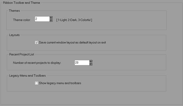
Ribbon Toolbar and Theme:
|
Field |
Description |
|
Theme color |
Set the general theme color to 1-Light, 2-Dark, 3-Colorful. See Elements of the PhotoModeler Screen. |
|
Save current window layout as default layout on exit |
When checked, any changes made to pane layouts will be stored with the default layout, and restored when PhotoModeler is started next. |
|
Number of recent projects to display |
Controls how many recent projects are listed in the Backstage Open > pane. |
|
Show legacy menu and toolbars |
Use traditional menu and toolbars rather than the default ribbon toolbar. Not recommended – this feature may be deprecated in future releases and legacy toolbars many not be supported. |
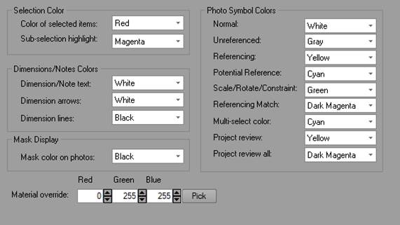
Colors:

|
Field |
Description |
|
Selection Color |
|
|
Color of selected items |
The color of items when user-selected on photos or in the 3D Viewer. |
|
Sub-selection highlight |
The color of items when associated 3D items are selected (e.g. the color of point marks on a photo when a 3D object point is selected). |
|
Photo Symbol Colors |
|
|
Normal |
The color of unselected marks on photos. |
|
Unreferenced |
The color of unreferenced marks on photos. |
|
Referencing |
The color used during referencing to denote items to be referenced. |
|
Potential Reference |
The color of the best referencing candidate during manual referencing. |
|
Scale/Rotate/Constraint |
The color used to denote the items active for the Scale/Rotate or Constraints when those dialogs appear. |
|
Referencing Match |
The color used to denote an item that appears to be a good candidate for a match during referencing. |
|
Multi-select color |
The color used to highlight items when multi-selecting in the 3D Viewer (i.e. when the mouse cursor moves over an item in the multi-select popup menu. |
|
Project Review |
The highlight color of the selected item(s). |
|
Project Review All |
The highlight color used to show all questionable items. |
|
Dimensions/Notes Colors |
|
|
Dimension/Note text |
The color of text for the Dimension or annotation text on photos. |
|
Dimension Arrows |
The fill color of arrowheads for dimensions on photos. |
|
Dimension Lines |
The color of lines connecting the arrow heads for dimensions on photos. |
|
Masks Display |
|
|
Mask Color on Photos |
The color of the mask display overlay on photos. See Draw Mask Mode and Create Masks Dialog. |
|
|
|
|
Material Override |
Used to override the material for display on photos, as set on the Visibility on Photos pane (see Visibility Settings). |
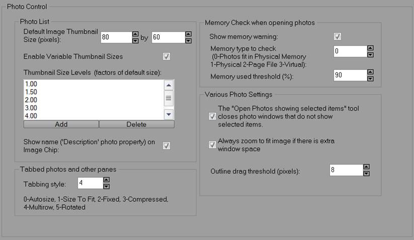
Photo Control:
|
Field |
Description |
|
Photo Control |
|
|
Default Image Thumbnail Size (pixels) |
Thumbnail or image chips are the small images shown in the Photo List Pane, the Add/Remove Photographs Dialog, and the Photo Table. The default size of these small images can be changed with these controls. This is useful for high resolution screens (to make the chips more visible). |
|
Enable Variable Thumbnail Sizes |
Controls whether thumbnails can be resized using +/- controls on the Photo List Pane’s toolbar. |
|
Thumbnail Size Levels (factors of default size) |
The size factor step levels used by the +/- controls on the Photo List Pane’s toolbar. For example, the first and smallest setting of 1.0 will result in a thumbnail equal to the default setting, while a 5.0 would show thumbnails 5 times as large, maintaining aspect ratios. Levels can be added or deleted if the default set doesn’t result in suitable thumbnail sizes. This affects the size of thumbnail images in the Pane and the Add/Remove Photographs Dialog. |
|
Show name (Description photo property on Image Chip |
If checked the filename is displayed along the bottom of image chips/thumbnails, in the Photo List Pane and on the Add/Remove Photographs Dialog. |
|
Memory Check when opening photos |
|
|
Show Memory Warning |
Controls whether a memory check is performed when opening photos using the settings below. |
|
Memory Type to Check |
Controls what type of memory is checked. Select “0” to check if the photo being opened fits in physical memory, or to check the amount of memory remaining (see threshold below): “1” for Physical memory (RAM), “2” for Page File, “3” for virtual memory. |
|
Memory Used Threshold |
The threshold at which a warning appears. When this percentage of memory is used up, the memory warning will appear (if enabled). |
|
Various Photo Settings |
|
|
The "Open Photos showing selected items" tool closes photo windows that do not show selected items. |
If checked, the "Open Photos showing selected items" tool will display only those photos showing the selected item and other windows will be closed. When not checked, all photos remain visible whether they show the selected items or not. Note that holding down the Ctrl button while the clicking "Open Photos showing selected" tool will do the opposite of this setting. |
|
Always zoom to fit image if there is extra window space |
If checked the photo window will automatically display the photo in as large a size as the containing window allows. |
|
Outline drag threshold (pixels) |
The number of screen pixels the mouse must move during the drag of an Outline before it is considered a Move. |
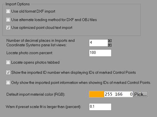
Image:

|
Field |
Description |
|
Marking Guides/Helpers |
|
|
Guarantee contrast of guide/ghost lines |
If checked all ghost/guide lines (line, curve, edge draw etc.) are drawn to guarantee contrast regardless of the image contents, although the contrast may be lower in some cases. |
|
No Xor rubber band during creation of silhouette/curves |
An xor (exclusive or) rubber band is the light gray line that follows the cursor during curve and silhouette marking. Some people may find the line distracting so here it can be turned off for both marking types. |
|
The thickness of the guide line displayed during surface creation (screen pixels, 0 - 10) |
Controls the width in pixels of the guide/ghost line used to outline the path in multi-point surface create. Setting to zero (0) will turn surface path guidelines off. |
|
Marking Snap To distance |
If the Point Marking tool is clicked within this distance to an existing Marked Point symbol, the position "snaps and a new point is not created. |
|
Resampling |
|
|
Resampling Type 3D Off |
Controls the type of resampling done during image display when no 3D items are shown. It can be set to Nearest Neighbor, BiLinear or BiCubic. The latter are slower but provide smoother display at high zooms. |
|
Resampling Type 3D On |
Controls the type of resampling done during image display when 3D items are visible. It can be set to Nearest Neighbor, BiLinear or BiCubic. The latter are slower but provide smoother display at high zooms. |
|
Photo Display |
|
|
Width of lines when set to 'thick' (screen pixels, 1 - 7) |
Controls the width of lines drawn on photos when the "thick" setting is checked in the Visibility Settings. |
|
Width of lines when set to 'thick' (screen pixels, 1 - 7) |
Controls the width of lines drawn on photos when the "thick" setting is checked in the Visibility Settings. |
|
Point IDs font size |
Controls the font size, in 'points', of the ID’s that display on photos. |
|
Dimension/Annotation font size |
Controls the font size, in 'points', of the Dimensions/Annotations that display on photos. |
|
Transparent point ID’s |
Controls whether point ID’s appear transparent. |
|
Show User Names as well as point ID |
When Point ID display is on (Visibility Settings or 3D Model Export Dialog) and this item is checked then a point’s user name will be shown also. |
|
Always show Scale/Rotate/Translate tags |
Photo marks display the scale/rotate/translate tags even if the External Geometry Explorer is not open. |
|
Rotate photos based on Exif information when adding to project |
If your photos have appropriate display rotation Exif data, the photo's rotation property (see Photo Properties) will be set so that the photo is displayed in PhotoModeler accordingly. |
|
Automatically assign mask files when loading photos |
|
|
Project sub-folder name |
The name of the subfolder in the images folder. |
|
Mask file names contain |
The tag that will be searched in the file name to assign to the appropriate photo in the project. See Texture and DSM Mask image file names for more information on masks. |
|
Save ICC Color Profiles |
Color profiles in images are stored during various image storing procedures. |
Photo Zoom and Pan:
|
Field |
Description |
|
Zoom |
|
|
Image Zoom Levels |
Controls the zoom levels used by zoom tools in photo display. |
|
Alt-Zoom Window |
|
|
Size
|
Controls the size of the Zoom-Window brought up by the ALT key. e.g. 100 means the window will be 100x100 screen pixels. |
|
Pan Speed |
Controls how fast the Zoom-Window pans when you move the cursor out of the window. (1 is slowest and 100 is fastest). Very fast machines may need lower values than default. |
|
Acceleration |
Controls how much the Zoom-Window pan speed accelerates as the cursor is moved farther outside the window. (1 means you have to move very far to get the pan speed to increase and 100 means you hardly have to move the cursor a few pixels away from the window for the speed to increase). |
|
Relative Zoom |
If checked, the Alt-Zoom window uses a relative zoom factor vs an absolute zoom factor. See below. |
|
Relative Zoom Factor |
The amount of zoom in the window when ALT is pressed as a factor. I.e. 2 means zoom 2 times from the current zoom. |
|
Absolute Zoom |
The amount of zoom in the window when ALT is pressed. This absolute zoom factor is a percent regardless of the photo’s current zoom level. |
|
Other |
|
|
Point Review Default Zoom |
Sets the zoom level for the photos shown in the Point Review Pane as a percentage. The default is 100%. Increase to zoom in closer to the reviewed point. |
|
Zoom around cursor position |
When Zoom lock is off, scroll wheel or other zoom will focus around the cursor position, rather than shift that cursor position to the center of the photo window. |
|
Scroll Zoom Factor |
Decreasing the scroll zoom factor (e.g. to 30) will allow for a smoother zoom with some mouse models. |
|
Scroll zoom only when mouse cursor in active photo pane |
This controls how a mouse scroll wheel change affects the zoom on the active photo. When checked, the mouse must be over the active image to zoom. |
|
Zoom lock default |
Engage zoom lock by default so that all open photos are zoomed at the same level simultaneously. |
|
Pan |
|
|
The number of milliseconds the mouse should be stationary before redrawing the image during pan (0-500) |
Controls the redraw speed of image panning (for pan mode and use of the scrollbars). Depending on the speed of your machine you may want to change this time delay setting. You can balance the speed of panning versus the quality of the pan. If you have a fast machine, try lowering the setting (perhaps to zero) to get high quality, smear-less panning or if you have a slow machine, and panning is too slow or not interactive enough, try increasing this setting. |
|
Real-time image pan update with scroller drag |
Controls whether the image in a photograph window is panned in real-time when the vertical or horizontal scroll bar is dragged. If turned off the image will refresh only after scrolling is stopped and the mouse is released. Note: You may want to change the time delay before the image repaints during a pan. See the Preference setting "The number of milliseconds the mouse should be stationary before redrawing the image during pan above. |
|
Use Ctrl key for temporary zoom/pan mode |
If checked, the Ctrl key will bring up the Temporary Zoom Area/Pan mode cursor when the mouse is over a photo, otherwise the Ctrl key will act in a standard Windows fashion. |
Photo Projections:
|
Field |
Description |
|
Projection Colors |
|
|
Points/ Lines/ Surfaces / Curves / Cylinders/ Edges |
The color of points, lines, surfaces, cylinders, edges and curves when projected onto photos if the above check box is not checked. |
|
Projections use object’s material (instead of these preferences) |
If checked, the projection of the model onto photographs is done with the object’s material (as in the 3D Viewer). Otherwise the colors in the following controls are used. |
|
Non-rendered Projections |
|
|
Non-rendered projections for: Points, Line, Control Points, Control Lines
|
The default projection mechanism on images is to use a full rendering and then merge with the photographic data. This mechanism can be quite slow and if your requirement is to only project point data (and sometimes lines) this option will give a faster and more accurate projection. Not all the same projection options are available in both cases though. |
|
Other |
|
|
Line Mode can select project points |
When in Line Mode with projected/3D points showing, projected/3D points can be selected. |
|
Cylinder projections are center lines |
Display projected cylinders as center lines in photos |
|
Show dark surface back faces |
Surfaces normally only render their front face in projections, so if the back of a surface is projected on a photo, you will not see the surface. Checking this option will render back faces of surfaces in a darker color. |

|
Field |
Description |
|
Clear the measure pane with each selection |
Each selection clears the measure pane of previous measurement values. |
|
Decimal places on the measure pane |
The number of decimal places to show for measurement data on the Measure Pane. |
|
Cylinder (see Measurement Information) |
|
|
Plane intersection angles |
Show the angle of intersection to the XY, YZ, XZ planes in degrees. |
|
Center line end points |
Show the endpoint coordinates of the cylinder center line. |
|
Center line vector |
Show the coordinates of the center line vector. |
|
Angles relative to axis |
Show the angle relative to the X Y and Z axes in degrees. |
|
Cloud/Mesh (see Measurement Information) |
|
|
Bounding Box for |
The bounding box center coordinate, and dimensions. |
|
Volume |
The volume of the Triangulated Mesh based on it being closed. |
|
Area |
The triangulated area of the Mesh. |
|
Volume between surface and XY plane |
The volume above and below the XY plane. |
|
Volume between surface and auto-close pane |
The volume above and below the auto-close plane. When a Mesh has an uneven hole, the best fit plane that is used to close it may not fit perfectly, so part of the mesh may actually lie below that plane. |
|
Plane Surface |
|
|
XYZ of plane corners |
XYS positions of plane corner points. |
|
Closest fit point |
Point ID of the closest fit point |
|
Volume above/below XY plane |
The volume of the region between the plane and XY plane. |
|
Other |
|
|
Point Measurements when a geographic coordinate system is defined also show earth centered coordinates |
Optionally, earth centered coordinates are shown below the geographic coordinate system. |
|
Show x,y,z of plane corners |
Optionally show the coordinates of the 4 corners of a plane. |