

Process:
|
Field |
Description |
|
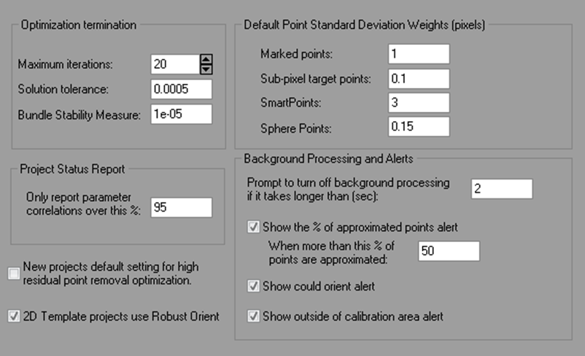
Optimization termination |
|
|
Maximum iterations |
|
|
Solution tolerance |
|
|
Bundle Stability Measure |
Some projects do not have a strong mathematical solution. Processing has trouble deciding what is the correct solution. A weak mathematical project (that is otherwise correct with correct references, good calibration, etc.) is an indication that results cannot be always trusted. In this case processing fails. The Bundle Stability Measure value itself is a matrix stability measure. It can be increased to 1e-3 from the default 1e-5 for example to make some mathematically unstable projects solve (i.e. complete processing). Long focal length calibrations are a project type that may benefit from this change. |
|
Project Status Report |
|
|
Only report parameter correlations over this % |
Controls which correlation values are shown in the Project Status Report. |
|
Default Point Standard Deviation Weights (pixels) |
|
|
Marked points |
|
|
Sub-pixel target points |
|
|
SmartPoints |
|
|
Sphere Points |
|
|
Background Processing and Alerts |
|
|
Prompt to turn off background processing if it takes longer than: (sec) |
The maximum length of time to perform background processing before being prompted to switch to manual processing. |
|
Show the % of approximated points alert |
A popup alert (bottom right of screen) will appear if the check box is checked, and if there are more than the specified percentage of points calculated only by approximation. |
|
Show could orient alert |
If checked, a popup alert (bottom right of screen) will appear when enough points are referenced for possible orientation. |
|
Show outside calibration alert |
If checked, a popup alert (bottom right of screen) will appear if a point is marked outside of the calibration point coverage area (i.e. the area of the lens that was solved during calibration). |
|
Other |
|
|
New project default setting for high residual point removal optimization |
This setting enables the automatic search and unreferencing of points with high residuals during processing. In addition, photographs may be set to 'do not use in processing' if they no longer meet the minimums. By default, the feature is on for Automatic Coded Target projects only. See also Total Error Dialog. |
|
2D Template projects use Robust Optimization |
The solution for 2D Template project set up uses the Smart Orient (Robust Optimization) which makes it more robust to errors in photography and targets. Some project might solve with this setting off. |
Orientation:

|
Field |
Description |
|
Orientation Point Counts |
|
|
Number of points to include in relative orientation |
|
|
Number of points to include in orientation check |
|
|
Valid orientation checks |
|
|
If roll angle is greater than __ use this weighting factor against the solution: __ |
|
|
If a projected point is closer to camera than __ use this weighting factor against the solution: __ |
|
|
Perform Angle Checks |
|
|
Fit Error Threshold |
|
Camera Calibrator:
The Camera Calibrator page controls the Camera Calibration process.

|
Field |
Description |
|
Custom Calibration Control Positions |
|
|
Four Planar Control Point Positions |
|
|
Auto-referencing |
|
|
Required number of photos to be referenced for each point in stage one |
|
|
Targets and Sub-pixel Marking |
|
|
Ratio of largest target in image to image size |
|
|
Ratio of smallest target in image to image size |
|
|
Targets are black on white background |
|
|
|
|
|
Include IDs when printing multi-sheet calibrations |
Show the target ID when printing calibration sheets for the multi-sheet calibration process. |
Self and Field Calibration:
The Process page controls those options to do with Processing and in particular Self/Full Calibration.

There are many settings here and their relationship to
processing is complex, so we give this whole section a caution sign ![]() .
While many of these settings are complex, they are important and for advanced
projects you may find yourself adjusting some of them. If after reading the
descriptions below you still require guidance please contact PhotoModeler
Technologies technical support.
.
While many of these settings are complex, they are important and for advanced
projects you may find yourself adjusting some of them. If after reading the
descriptions below you still require guidance please contact PhotoModeler
Technologies technical support.
|
Field |
Description |
|
Camera Calibration (self or field) |
|
|
Calibrate when greater than these number of good points on all photos |
|
|
Calibration in one camera projects is a full field calibration (otherwise self-calibration) |
If checked, and there is only one Camera assigned to all photos in the project then a field camera calibration is done instead of a self-calibration. See Field Calibrating and Field Calibration. |
|
Self-calibration uses Std. Dev. Weights |
|
Imports/Control:
|
Field |
Description |
|
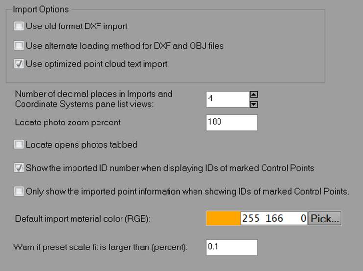
Use old format DXF import |
Check this if you’re having difficulties with the DXF file import, as the ‘old’ system may be more compatible with the model entities. |
|
Use alternate loading method for DXF and OBJ files |
When checked, the import uses the ‘FBX’ loading system rather than PhotoModeler’s native system. |
|
Number of decimal places in… |
Controls the number of decimals shown in the list views of the Imports and Coordinate Systems Pane. |
|
Locate photo zoom percent |
The zoom percentage of the photo that opens when showing the ‘located’ point. |
|
Locate open photos tabbed |
When checked and when multiple photos show the ‘located’ point, the photos open tabbed, otherwise they’ll open tiled in the Photo Windows pane. |
|
Show the imported ID number when displaying IDs of marked Control Points |
When checked the imported ID number will be displayed along with the control point name on control points marked on photos. |
|
Only show the imported point information when showing IDs of marked Control Points |
When checked only the imported ID number will be displayed on control points marked on photos. |
|
Default Import Material color |
Set the Material color automatically assigned to imported objects. |
|
Warn if preset scale fit is larger than (percent) |
A threshold to flag potentially bad scale(s): A) Warn when a Coded Target Preset is set on a project and a scale error is larger than this value. B) During export to note scale may not be correct. C) Used by Check Distance table to bold distance errors (%) that are larger than this value. |
Control Orient Inverse Camera:

|
Field |
Description |
|
Do exhaustive control orient search when fewer than these number of control points |
|
|
Inverse Camera Parameter Standard Deviation Weights |
|
|
Use Standard Deviation Weights during calibration of InverseCamera parameters |
|
|
Inverse Camera Parameter Standard Deviation Weights |
|
|
Thresholds for minimum number of control points |
|
|
Basic minimum |
|
|
For inverse focal length |
|
|
For inverse principal point |
|
|
For inverse format size |
|
|
Minimum % image coverage by control points |
|