

General:
|
Field |
Description |
|
Startup |
|
|
The application should restore it's last size and position upon starting |
If checked, PhotoModeler will reopen each time in the position and size when it was last closed. |
|
Decimal Places displayed |
|
|
Decimal places in dimensions |
The number of decimal places to show in on-photo dimensions. See Adding Dimensions and Annotations. |
|
The number of decimal places to show in the various Properties Panes. |
|
|
General Application Settings |
|
|
Acknowledge DDE commands |
|
|
Use check box for boolean property grid values |
If checked, checkboxes appear on Property grids, otherwise text TRUE or FALSE appear. |
|
Decimal places in dimensions |
The number of decimal places to show in on-photo dimensions. See Adding Dimensions and Annotations. |
|
Update check interval |
The number of days between checks made online for updated versions of the software. Setting this to zero (0) means no checking for updates will be done. |
|
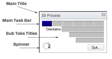
Show status/progress animated system tray icon |
When checked, a small animated icon will display on the Windows system tray when a progress dialog is showing. This helps notify you that an operation has completed, for example when switching applications during a long and complex operation (e.g. when generating a large and dense DSM, or processing a very large project), the icon will tell you if the operation is still underway. The animated icon does consume resources so you should weigh the benefits of staying informed of a PhotoModeler operation and the effect of the icon on overall performance of the operation. |
|
Clear selection at start of scale/rotate wizard |
Clears the selection of items when starting the Scale and Rotate Wizard, which prevents inadvertent assigning of points to scale/rotate elements. |
|
Use CTRL for multiple selections |
This switches the default key from Shift to Ctrl for use with Multiple selection of items in photos, and therefore also switches the CTRL Zoom function (see Temporary Zoom / Pan Mode) to Shift-Zoom, i.e., the Shift and Ctrl keys are flipped within PhotoModeler. |
|
Tables |
|
|
Decimal places for Table data |
Controls the number of decimal places shown in numerical values in tables. |
|
Open table planes tabbed |
When opening a table, the table will tab with already open tables. |
|
Exponent Threshold |
Values smaller than this threshold will display in tables using exponent notation, e.g. 1.05E-5. Values larger than this threshold will display in decimals, e.g. 0.0000534. |
|
Exponent Decimals |
The number of decimal places shown when tables values are displayed in exponent form. |
|
Pane Activation (Mouse-in) |
|
|
Mouse-in activates photo |
Check to enable activation of a photo pane when the mouse cursor enters the photo. Otherwise activation requires a mouse-down/click. |
|
Mouse-in activates 3D Viewer |
Check to enable activation of a 3D Viewer pane when the mouse cursor enters the 3D Viewer. Otherwise activation requires a mouse-down/click. |
|
Mouse-in activates table |
Check to enable activation of a table pane when the mouse cursor enters the table. Otherwise activation requires a mouse-down/click. |
|
Threads |
|
|
Number of cores to use (0 = all) |
Various features in PhotoModeler are 'multi-threaded' meaning multiple tasks can be carried out simultaneously. The number of tasks depends on the number of cores or processors on your computer. This setting controls the number of cores to use while performing multi-threaded operations. Setting to 0 will allow all cores to be used. |
Project:
|
Field |
Description |
|
Project Default Settings |
|
|
Default Project Units |
The units that are set by default when a new project is started. |
|
Layers… |
The set of Layers for each new project. See Layers Added to All New Projects. |
|
Materials… |
The set of Materials for each new project. See Materials Added to All New Projects. |
|
Project Backup |
|
|
Maximum backup versions (_verN) |
Controls the number of backup version pmr files that are saved. |
|
|
|
|
Use sub-selection highlighting |
Controls whether a mark (e.g., 2D point mark) is highlighted in the sub-selection highlight color when it’s associated object (e.g. 3D Object Point) is selected. |
|
Speed up undistort by saving the .ldl cache file |
Controls whether the undistort .ldl cache file is saved with the project or recreated each time it is needed. |
|
Enable Project Review Status icon on status bar by default |
Controls whether Project Review Status icon enabled by default, which prompts for review when certain conditions are met (see Project Review Pane). This can be enabled on the Project Information Dialog. |
|
Add a line between the point and offset when a new one is created using the Properties pane |
Automatically draw a line between a point and it’s offset at the time it’s created. See Properties Pane or Properties of Selected Dialog. |
|
Offsets use a cross symbol |
The projected offset point displays with a cross symbol rather than the usual point symbol. |
|
When a project opens also open |
|
|
Photo List |
Controls whether the Photo List Pane will display when a project is opened. See also Manage Layouts Dialog. |
|
Photo 1 |
Controls whether the first photo in the project will open when a project is opened. See Photo Windows Pane, and Manage Layouts Dialog. |
|
3D View |
Controls whether the 3D Viewer will display when a project is opened. See also Manage Layouts Dialog. |
|
Visibility Pane |
Controls whether the Visibility on Photos will display when a project is opened. See Visibility Settings, and Manage Layouts Dialog. |
|
Properties Pane |
Controls whether the Properties Pane will display when a project is opened. See also Manage Layouts Dialog. |
|
Measure Pane |
Controls whether the Measurements Pane will display when a project is opened. See also Manage Layouts Dialog. |
|
Imports and Coordinates |
Controls whether the Imports and Coordinate Systems Pane will display when a project is opened. See also Manage Layouts Dialog. |
Curves and Surfaces:

|
Field |
Description |
|
Tessellations (3D Viewer and export) |
|
|
3D Curves are tessellated to within this percentage of the project size (0.0001-5.0) |
Controls the tessellation tolerance for NURBS curves that are converted to line segments for the 3D Viewer AND for those 3D export formats that do not handle native NURBS. |
|
Objects are tessellated so that no triangle has an angle greater than this with neighbor triangles (degrees) |
Controls the tessellation tolerance for NURBS Surfaces and Cylinders that are converted to triangles for the 3D Viewer AND for those 3D export formats that do not handle native NURBS. A smaller value means more triangles and a finer tessellation. 25 degrees works well for cylinders, but a smaller value (such as 10 degrees) works better for surfaces. |
|
General Surface Settings |
|
|
Surfaces default to double sided |
If checked, all new Surfaces have their "double sided" property turned on. |
|
General Curve Settings |
|
|
Curve algorithm tessellation tolerance (pixels) |
|
|
Best Fit Plane Settings |
|
|
Maximum distance a point can be away before a warning is displayed. |
If a defining point measures above or below the calculated plane by this amount (in mm), a warning will appear, which indicates that the set of points used to define the plane may not actually be planar. |
|
Default Offset |
If a plane is defined by target that are raised above the surface this offset value adjusts the calculated plane down to the actual surface. For example, the defining target points are 4mm thick rubber backed targets – the offset value in mm would -4, to drop the plane down to the actual surface. See Plane Offsetting. |
|
Allow Surface Draw |
If checked, Best Fit planes can be defined by Surface Draw points. |
|
Other |
|
|
Deleting a surface draw curve deletes the points used to define it. |
If not checked, the defining surface draw points remain marked on the photo. |
|
Allow Surface draw lines over multiple photos |
If not checked, extending Surface Draw lines across photos will not be possible. |