

The Shape Relation dialog is used to define or refine shape relations. The dialog appears automatically when new shapes are added (after the base shape) or it can be brought up from the main application’s “Add Shapes” toolbar using the “Add Relation…” tool.
Note, the “Add Relation” tool on the “Add Shapes” toolbar is enabled when an appropriate component of the shape is selected in the Shapes Explorer 3D or List view. See Selecting Shapes and Shape Parts.
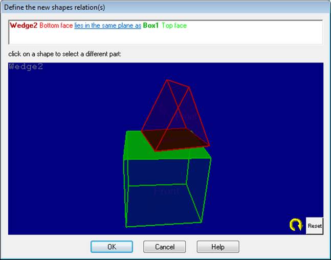
The dialog has two sections. The top section is a rich-text control that describes the relation textually and may have hyperlinks to modify the relation. The bottom section is a 3D view that shows the one or two shapes being related. You click on the shapes in this bottom 3D view to make certain types of relation changes.
In the example above a box shape called Box1 was selected and then a wedge shape was added to the project. The dialog automatically appears and assumes that you want to place the bottom of the wedge on the top of the box. If this is correct you can press the OK button and proceed with the marking of the wedge.
You may not want this default choice though. If you wanted instead that the wedge sit on the ground plane you can click on the relation-type hyperlink lies in the same plane as and from the menu that appears pick the “lies flat on ground plane” option. You can make a similar change to tie this shape to 3D points.
The coplanar relation may be the relation you want but the face may be incorrect. In this case click on the box in the 3D view and a menu of face names will appear. As you mouse over these menu items the faces will highlight in the 3D viewer to give feedback as to your choice. You could choose “Right face” for example so the bottom of the wedge will sit on the box’s right face.
You can also change the face of the new shape at this time but a wedge can use the bottom face for coplanar relation only. If the new shape was a box or a truncated wedge then you could pick a different face for it also.
You can also refine the coplanar relation further at this stage. (Note you can come back later and refine the relationship between the two shapes). If you click on the relation-type hyperlink lies in the same plane as you can choose to add refinement relations (clicking on the relation in the menu toggles it on or off and you select a relation in the menu to activate or deactivate it – to activate multiple relations, click the hyperlink again to toggle a relation). Below we have set to use the Box1’s front face, and made the two faces coplanar, have the same center axis (concentric) and be aligned. This can all be done before marking is done on the wedge and this is used by the shape algorithm to improve the shape’s position and rotation.

Often it is advisable to pick the minimum relations for a new shape (e.g. choosing one coplanar or ‘lies on ground’) to start. After the shape is solved you may wish to refine it further. In this case you can select a single shape or two shapes to refine the relations. select edge marks in photos or edges and faces in the 3D viewer and then press the Add Relation tool in the Add Shapes toolbar. See Selecting Shapes and Shape Parts for more information.
Also see the section on the Parameter Equal Relation as this relation has some additional capabilities and user interface.
Shape Relations can also cause trouble with the model and the solution. You can add relations that conflict or you can add relations that are not true on the real world object (i.e. adding a concentric relation when the shapes in the real-world are actually offset). Sometimes these conflicts will cause the solution to become slow and sometimes it will fail. See the Troubleshooting Shapes section for more information.